The Hoot-Vega Radio Telescope
The Hoot-Vega Radio Telescope
did not just happen. Its creation is the fusion of interests,
inspirations, and support that goes back to my childhood. I have
been a radio enthusiast for fifty-five years and amateur
astronomer for more than fifty years. In some ways it is
surprising that it has taken this long to fuse those interests
together into this project. It still would not have happened
without the generous support of my family and Dr. Eduardo Vega.
Additionally, I want to acknowledge the hard work of the craftsmen
whose efforts went into building the telescope. Special thanks go
to Bruce Stevens and Jerry Grace, consummate craftsmen and easy
working companions. Their many excellent suggestions have made the
HRVT a better instrument than I had imagined. I would like to
extend my thanks to these people and the others who have been
there to support and encourage me during its development.
John
E. Hoot
25 August 1999
San Clemente, CA
Postscript: Sadly,
Dr. Eduardo Vega pass away in 2003. His observatory and this
instrument have gone through several ownership changes and, to the
best of my knowledge, is no longer operational. I miss his
enthusiasm and generous spirit.
Subsequent
Developments
After about a year of design and
development the HVRT tooks its first astronomical observations on
August 21, 1999. Telescope commissioning observations and images
are posted here. The formal dedication of the telescope and an
introductory seminar on Radio Astronomy were presented at the HVRT
site in early October of 1999..
Observation
of Radio Sources 3C310 and 3C315
The first astronomical
observations made with the HVRT were made as transit observations
of extragalactic radio sources 3C310 and 3C315. These observations
were performed with the following scope settings:
Gain = 20
Integration
Time = 10 second
Sample Interval = 5 seconds
UTC Interval =
23:55Z … 00:30Z
Declination = 26 degrees
This observation was made to
determine the sensitivity of the instrument. According to the
Cambridge Survey, the instrumental fluxes of 3C310 and 3C315 are
46.0 and 18.8 respectively. Below are two figures, the HVRT plot
and a graphical representation of the same object taken at 1421MHz
with the Bonn Radio Telescope. They are shown at approximately the
same horizontal scale.

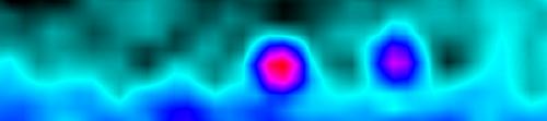
The strong correlation between
these two figures, is compelling evidence that the HVRT has
sufficient sensitivity to detect and image sources with Cambridges
fluxes of 15 or more.
HVRT Overview
The HVRT is not a single radio
telescope, but a collection of antennas, feeds, receivers,
detectors and digitizers that can be used to make both geophysical
and astronomical observations. It is more akin to a set of radio
tinker-toys than to a single instrument. I will outline its
primary configurations and uses, but do not let those constrain
you. The HVRT can be configured to perform observations never
envisioned by the author of this manual.
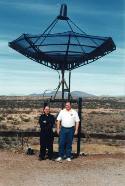
Physically, the HVRT is located
in the Vega-Bray Observatory at the Skywatcher's
Inn in Benson Arizona. The telescope is a complex instrument
and needs to be run by a trained operator. Access to the
instrument is controlled by the staff of Skywatcher's Inn.
The HVRT is composed of three
different radio receiving systems.
Steerable
Microwave Receiving System configurable to receive at 1421 MHz,
4.0 GHz and 11 GHz.
An
omnidirectional integrating short-wave receiving system covering
0.5 MHz - 30.0 MHz
A fixed 1691 MHz
geostationary meteorological satellite receiving system.
Design
Objectives
The HVRT was designed to meet
several objectives and requirements. It is to act as a teaching
instrument. It will be used routinely to demonstrate to
observatory guests the function and purpose of radio telescopes.
To
act as a test bed for exploring the capabilities of an modestly
priced radio telescope
To
be a test bed for remote radio observing
To
operate as either a transit instrument or stare mode telescope
To
provide all sky coverage
To provide a basis for
expansion into an interferometer for high resolution observing.
The instrument that emerged from
these requirements is summarized in the sections below. Each
instrument group's function and major components are outlined.
Detailed design descriptions for each instrument cluster can be
found later in this manual.
Microwave
Instruments
The microwave portion of the
HVRT is divided roughly into a front-end subsystem and back end
subsystem. The front end subsystem performs signal acquisition.
The backend system decodes and analyzes the signals from the
front-end system. The entirety of front-end system is located at
the antenna site. It is connected to the backend system via a set
of underground cables. The backend system is housed in the control
room of the 20" telescope at the VBO.
The Front End Sub-System
The
front-end system consists of the antenna, its positioners, feed
horns, and RF amplifiers and down converters. The block diagram
below depicts its major components.
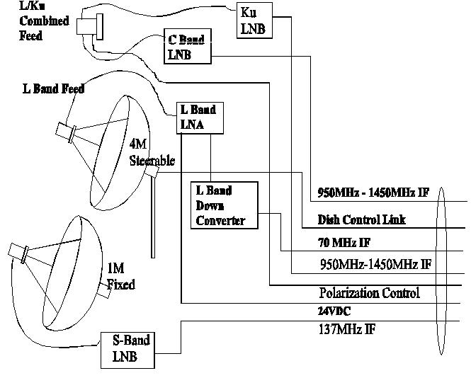
The sections below describe the
function of each of the components in the system.
Steerable 12 Foot Parabolic
Reflector
The 12' parabolic reflector collects RF energy
and focuses it at the feed point of the antenna. The antenna is
mounted on a hitching post mount. This steerable mount allows the
antenna to be pointed to nearly all sky locations. A heavy duty
TVRO dish was adapted for use as the parabolic reflector. This was
the most cost-effective way to obtain a dish with a figure good
enough for use up to 11 GHz. For details on the pointing system,
see the section on the antenna mount, and drive control system.
Feed Horns
Feed Horns
are devices that collect radio energy at specific frequencies and
direct it into cables or wave guides that in turn carry the energy
to the electronic of the receivers.
Two different feed
configurations will be supported. A 1421mhz L-Band feed with LNA
and downconverter will typically be mounted on the system. This
feed can be removed and replaced with a combined C and Ku band
feed system covering 4 GHz and 11 GHz bands. It will collect C and
Ku band TV signals, as well as C and Ku band radio astronomy
signals. Mounting a different feed horn entails rotating the dish
down and physically changing the component at the antenna focus.
Usage of the different feeds is
summarized below:
|
Frequency
|
Usage
|
|
1421 MHz
3 degree resolution
|
Image Galactic
H-II regions (Orion, M16, ...)
Solar
Observing
Milky Way
|
|
3700/4200 MHz
1 degree resolutiuon
|
Synchrotron Radiation
Pulars
Black Holes
Neutron
Stars
|
|
11000 MHz
20 acr minute resolution (need dry days)
|
Synchrotron Radiation
Pulars
Black Holes
Neutron
Stars
|
1420 MHz LNA
This is a
low noise amplifier tuned to the emission frequency of neutral
hydrogen. It amplifies the weak signal at the antenna to minimize
signal loss in cables.
1420 MHz Downconverter
The
downconverter translates the received signal from 1420 MHz down to
70 MHz. Moving the signal to a lower frequency simplifies the
transmission, amplification and decoding of the signal.
C Band LNB
This low
noise block down converter integrates an LNA and block down
converter into a single device. It translates the signals in the
range of 3.7 GHz to 4.2 GHz to 950 MHz to 1450 MHz. In addition
this device has a signal polarization controller. This can be
useful looking at polarized radio sources and is essential for
decoding TVRO satellite signals.
Ku Band LNB
This low
noise block down converter integrates an LNA and block down
converter into a single device. It translates the signals in the
range of 11.1 GHz to 11.6 GHz to 950 MHz to 1450 MHz. In addition
this device has a signal polarization controller. This can be
useful looking at polarized radio sources and is essential for
decoding TVRO satellite signals.
Back End Sub-System
The
backend system contains the primary operator control point for the
telescope and performs all the signal processing and decoding. A
block diagram of the major components is shown below:
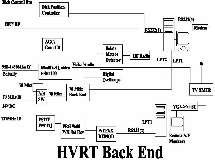
The back end sub systems
contains the following major components:
BSR1100 Receiver
This
is an off the shelf C/Ku band satellite receiver. It was selected
for its moderate cost, variable bandwidth, 70 MHz IF frequency and
ease of modification. The receiver performs dual duty. It will
receive and decode standard TVRO signals when the telescope is
used as a TV receiver. It can also be used as the Ku and C band
receiver for radio telescope when the modifications are enabled.
The receiver is modified to
include an external RF gain control. This disables the automatic
gain control system used when receiving TV with the unit. A tap
will be made to the 70 MHz IF to bring this signal out where it
can be fed to the radio telescope 70 MHz backend.
70 MHz Backend
The 70
MHz backend contains RF amplification, a wide bandwidth product
detector and analog to digital converter with adjustable gain and
integration time constants. It conditions the received signals for
the computer.
Antenna Mount Controller
The
antenna mount controller allows the user or computer to point the
antenna at various parts of the sky. For details on this device,
see the associated white paper.
The Short-wave Monitoring
System
The short-wave monitoring system is used for
geomagnetic and solar flux sensing. It may also be adapted to
meteor scatter observing. It consists of the following main
component:
Fiberglass
exterior whip antenna
RG58
Feed Line
AC/DC
LW-MW-SW-FM receiver
Signal
Integrator
Digital Oscilloscope &
Chart Recorder
The digital oscilloscope and
chart recorder offer the ability to digitize signal
characteristics over long periods of time and is useful for the
general maintenance and calibration of the system. Facsimiles of
the operating documents for these items can be found in the
appendices to this manual.
The Weather Satellite Imaging
System
The weather imaging system consists of a 1 meter
dish, feed horn, LNB, scanning satellite receiver, decoder,
computer system and software. This system runs continuously,
downloading imagery and displaying it on an NTSC video monitor
with the ability to transmit this imagery over short distances
with a low power TV transmitter. This system allows remote earth
observation and the creation of dynamic video loops.
The Computer Systems
There
are two separate computers at the site. One computer is dedicated
to the Meteorological Satellite receiving system. It is an older
286 PC running MS-DOS 5.0. It is dedicated to the continuous
reception of weather satellite imagery that is presented on a TV
monitor at the work station and broadcast over a short haul radio
link for reception in the media room of The Inn.
The other computer is the
primary control and data acquisition computer for the microwave
and short-wave instruments. It can be operated from the operator's
position or can be controlled by a remote user
The primary computer's
function's include:
Data
Acquisition
Power
Control for the Instrument Racks
Position
the Microwave Receiving Antenna
Digitizing
Radio Signals
Analyzing
and Presenting Data
Locating
Objects From Catalogs
Sky
Map Presentation
Remote
User Support
Remote User Verification
The primary computer is
currently an IBM Compatible PC running Microsoft Windows 95. The
present configuration includes:
486DX25
CPU
8
Meg RAM
210
Meg Hard Disk
4
serial ports
2
Parallel Ports
Mouse
CD-ROM
3.5"
1.4Meg Floppy Disk
External
56K BPS Modem
101
Key Keyboard
SVGA Monitor
The relatively modest computing
power of this system is adequate to its purpose. As more powerful
machines become cheaply available, it will undoubtedly be
upgraded.
The computer will be configured
to concurrently run several different programs:
HVRT Control Program
This
is a Windows based program that acts as the central control point
for the telescope. It handles pointing, data acquisition,
unattended operation, data reduction and analysis. It allows you
to point the telescope to a specific RA/DEC, ALT/AZ, catalog
object, Meridian Transit position or Geostationary satellte
location. The program will digitize data from the 70 MHz backend
receiver. This information may be displayed graphically on the
display and/or saved as a stream of position and flux readings to
ASCII text log files for subsequent analysis. The program will
create FITS files from the flux observations.
Scope-It
Digital Data
Recorder programs for the PC to store the output from the 70 MHz
telescope backend and from the short-wave monitoring system. It
includes a FFT (Fast Fourier Transform) mode for pulsar period
measurement and a long duration chart recorder useful for timing
pulsars.
FitsView
This is a
freeware program from the NRAO. It allows you display and
manipulate FITs format images. It is invoked directly from within
the HVRT Control Program
SK2000
A planetarium
program customized to feature the CAMBRIDGE 3Cxx catalog of
celestial radio sources. This will allow you to pick objects to
view and calculate their current positions.
Hidden Image
A program
to perform maximum entropy deconvolution on FITS files. The idea
here is that if we can exactly calibrate the antenna pattern
(equivalent of the optical PSF) we can get a 3x or 4x improvement
in resolution in our images by using Maximum entropy deconvolution
on our images. This will yield 15 arc minute resolution at 4 GHz
and 5 arc minute resolution at 11 GHz.
PC-Anywhere
This
commercial program allows remote users, connected via a modem or
over the Internet to control the telescope computer as though they
were at the console. Additionally, it provides a fast file upload
and download facility to allow remote users to retrieve their data
files.
|